I needed to drill and bore a hole in a square-ish piece of stock. The only piece of machinery I have that is even remotely capable of doing that is the lathe. I do however only have a three jaw chuck for it. Buying a four jaw chuck for some 60 Euro is certainly an option – but why would you buy a decent product for a reasonable price, when you can spend twice as much money and a dozen hours of your time making something that works a lot worse?
Here is the idea – I can make a backplate that’s roughly 120 mm in diameter. Onto that plate I can affix two steel blocks. These blocks will hold two moving jaws (sliding on pins acting as guides) that can be tightened with a regular screw. Planned capacity of this “vise” was about 50 mm, which is a little more than I actually needed for the project I had in mind.
Here’s a Fusion360 rendition:

Let’s break it down into components:
The backplate
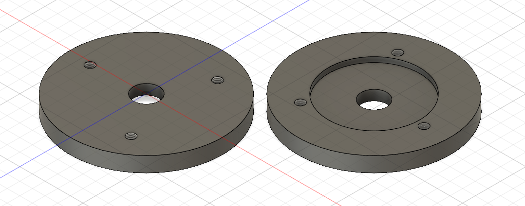
The 120 mm diameter is just about the capacity I can turn on my lathe. There are three holes for attaching the plate to the spindle, and an inset ring to locate and center the plate on the spindle.
The jaw holders

These are made from 15x20x80 mm cold rolled steel – without a mill (or patience and skill) I deemed this to be the best and easiest way to get relatively precise stock to make these parts. There are two 10 mm holes for the sliding pins and one M10 threaded hole in the face of the block, and two countersunk clearance holes for M6 screws (for attaching the block to the plate). I used regular 10 mm drill for the pin holes and then “reamed” them with shopmade reamer made out of round HSS blank, that is 9.99 mm in diameter. Obviously you want the inside of the holes to have a nice finish for the pins to slide easily.
The jaws

Made out of the same 15x20x80 mm cold rolled steel stock. This time the shorter side is facing the backplate. There are two M8 threaded holes for attaching the sliding pins. It’s best to transfer the centers of these holes from the respective jaw holder. The pins (4 in total) should be turned to match the drilled holes in jaw holders. I polished them with sandpaper up to 1200 grit.
The result
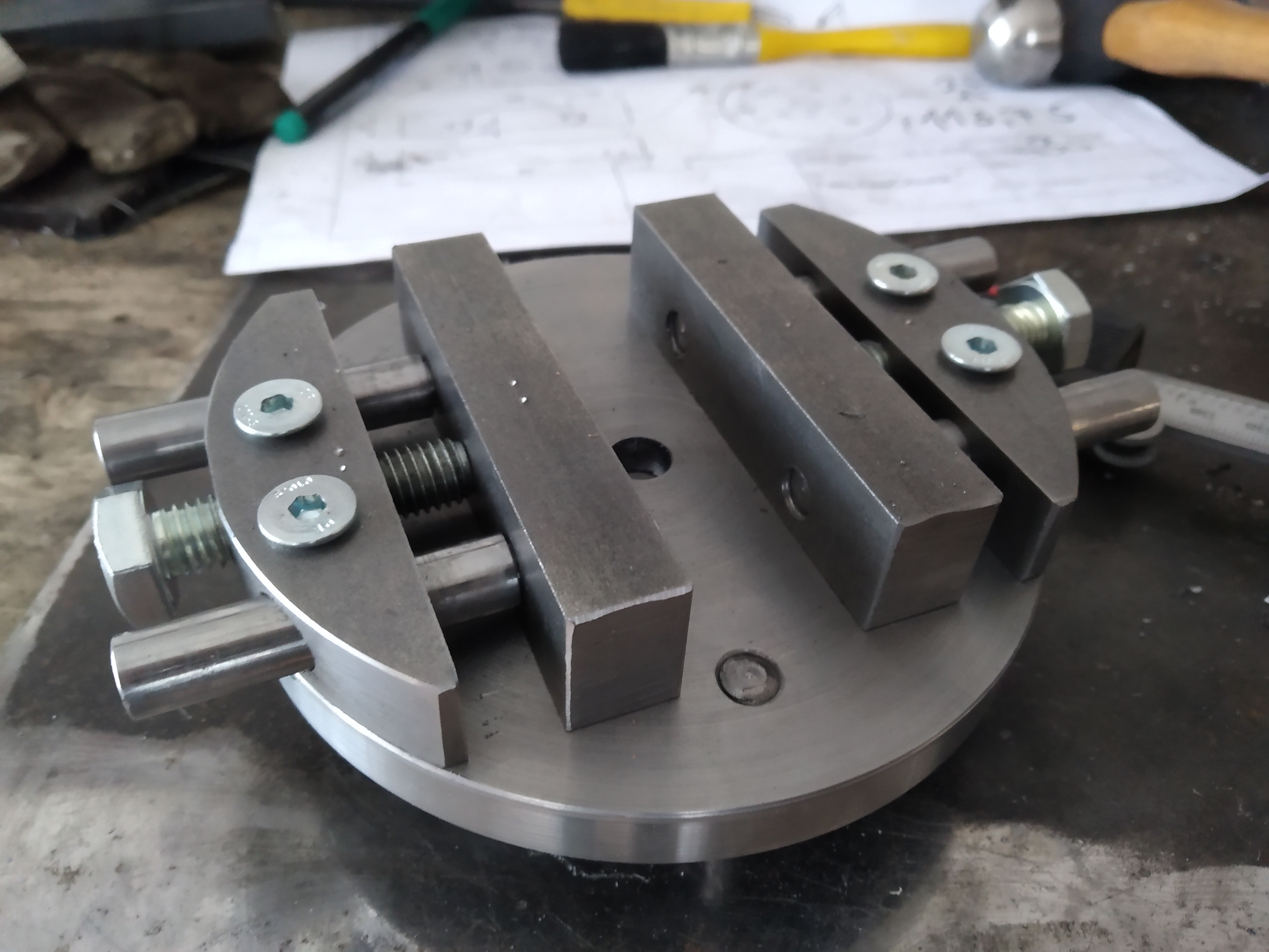
As you can probably tell, I botched a LOT of things. The jaw holders are not centered on the plate, the sliding pin holes do not align with the pins quite well and are not square, resulting in some binding when the jaws move.
It does, however, WORK.
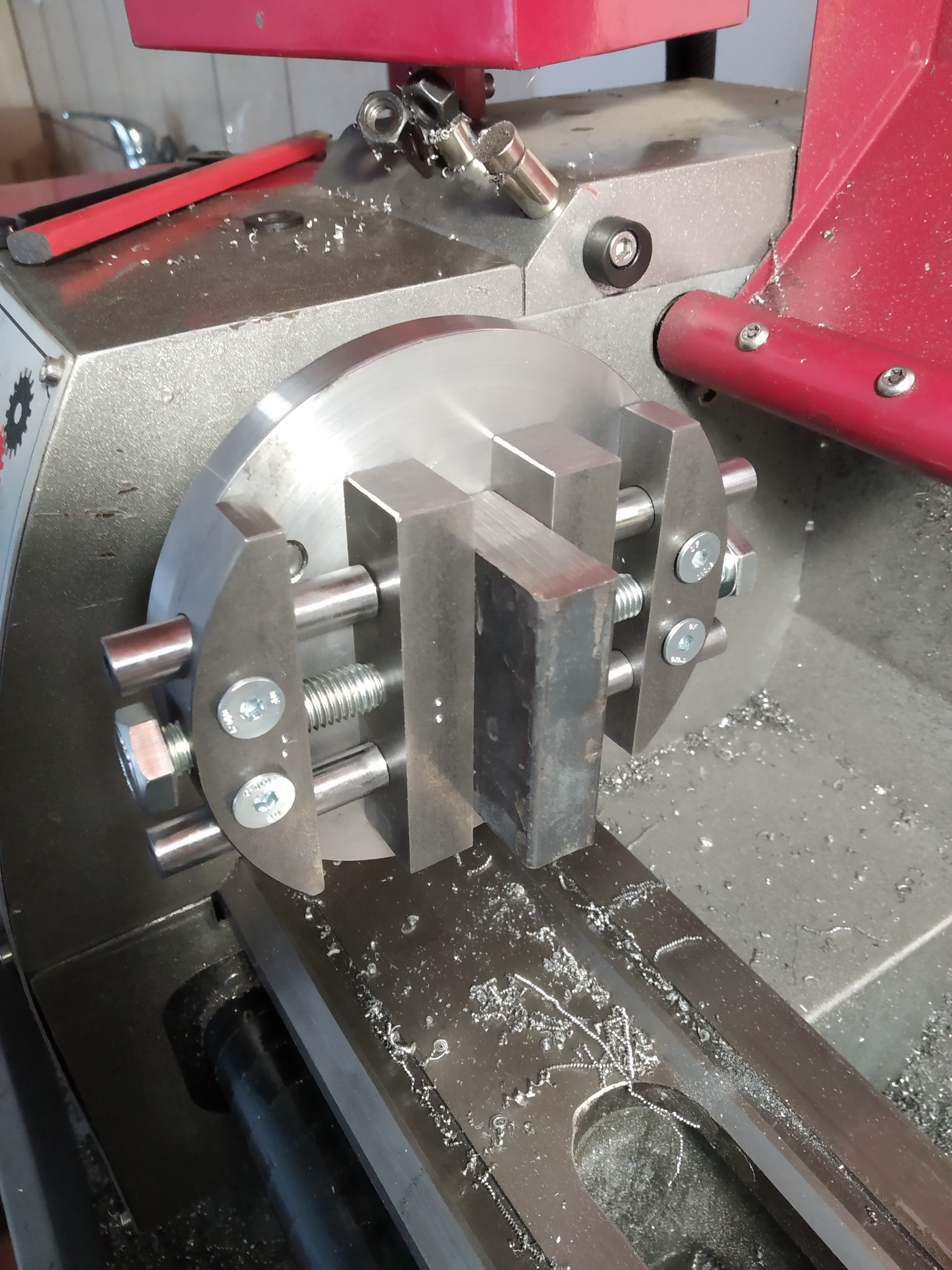
I did not dare to turn the RPM higher than 350, as it caused a lot of vibrations. That speed was still sufficient for some facing cuts and drilling/boring.
The jaws tend to lift up from the plate when using some spacers between the workpiece and the backplate, which is probably to be expected from this kind of design (given the amount of slop in the pins/holes). This will of course affect the precision that can be achieved. The gripping strength was sufficient for 0.2 mm DOC facing cuts, which is fine for what I’m doing.
Thanks
-Pavel
0 Comments